Help needed with W540 fried backlight circuit
Posted: Fri Apr 17, 2020 2:17 pm
Hello,
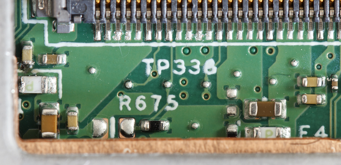
a few days ago I accidentally fried the backlight circuit on my W540 by not noticing the battery was still in while un-plugging the LCD panel connector directly at the panel. At first I thought the whole panel was dead, but then noticed that only the backlight did not work. So I disassembled the W540 to a point where I could do some measurements on the backlight circuit near the 30-pin eDP connector. It turned out that the backlight fuse F11 (0603 3A 32V) had blown leaving the eDP connector without backlight power. I measured the connector side of the fuse for shorts to ground but did not find anything, which hopefully means that just the panel connector shorted upon un-plugging which blew the fuse and everything else is OK. The other side of the fuse, connected to an HP8K22 power mosfet on the other side of the board, also shows no short to ground. When powering the W540 up, I get a voltage reading there of 19V to 20V, which seems to be the supply voltage of the power supply. However, at this point I kind of expected 12 volts for powering the backlight. Also I get the 20 volts as soon as the power supply is plugged in and not only after if I push the power button. The panel specifications at panellook state a default voltage of 12V and a maximum of 21V for the panel. Does anyone know if the 20V reading at this point is expected and the panel is powered on only via a signal on the eDP enable pin? At the moment, I am kind of hesitant just replacing the defective fuse (most likely a Panasonic ERBSE3R00U) with a ERBRE3R00V. I don't want to damage the panel if it is still OK. Does anyone know if the schematics of the W540 are available somewhere? Searched the net but could not find anything.
Kind regards